Motion capture is more than attaching some cameras to a frame grabber. A reliable imaging system requires careful thought to the imaging environment, lighting, calibration, hardware and software. This web page describes how these issues are addressed within the GTMS optical tracking system at the University of Michigan.
Note: click on images to enlarge
Because GTMS is based on calibrated computer vision techniques, the imaging environment, or arena, can be controlled for best possible performance. We use, of course, black backgrounds to improve the contrast. Below is a picture of our arena, with cameras and lighting mounted to a rack on the ceiling, and the arena below. To the right is a desk that holds our computer, video monitors, and lighting controls. The calibration stands are shown in between the arena and the vision computer.
Not only should the arena be properly dark, but the markers should be properly bright. For this purpose, we use the retroreflective tape manufactured by 3M to make the bright markers. In this photo can be seen the markers mounted on the RHex mobile robot. In addition to darkening the arena, the robot has been darkened to remove the possibilities of spurious features being identified by the tracker.

Proper lighting is critical for achieving reliable optical tracking. The most popular method is to use bright infrared LED's, together with infrared bandpass filters on the cameras. However, we currently use the low tech solution of multiple incandescent lights mounted on both sides of the camera. The incandescent lights are mounted within aluminum reflective cones to maximize the amount of light directed toward the target. This setup is very low cost, much lower than industrial machine vision lighting, but has some disadvantages that we have less control over lighting directions.


In addition to the imaging environment and lighting, you must configure the video hardware. We use analog CCD cameras, which are connected to a Pentium II class computer that houses two Data Translations frame grabbers. The camera videos are fed into monitors which are useful for rough positioning of the robot, tweaking the lighting, debugging the software, and so on.


Cameras are genlocked (synchronized in time) using Sony junction boxes.

To facilitate turning on and off the lights, we have a remote control system.


The calibration procedure involves placing markers at known locations within the arena, capturing the images, and then running the calibration software. The positions of the calibration markers should be chosen so that they approximately fill the sensing volume. This means, in our case, that the markers must span the 2d area that RHex will run across, and must be approximately as low or as high as RHex can sit, run or jump.
Below are seen the calibration marker positions for our arena. Three seperate calibration images are taken. In the first image, the markers are placed on ground level. In the second image and third images, markers have been mounted on stands of known height, and then positioned within the arena.


In total, six calibration images are captured, two images for each camera. The images are then processed by software to locate the markers, and then each identified marker is manually corresponded with one of the 3D positions. From these correspondences, the camera calibration matrices are computed.
Here is a closeup of the calibration stand. Note the plumb weights underneath the markers used for positioning.

The GTMS software was written by our group for stereo motion capture. It runs on a linux workstation with two data translations DT3155 frame grabbers. Routines support simple and template based feature detection, multiple hypothesis tracking to handle spurious features and occlusions, automatic stereo correspondence selection, and 3D reconstruction.

The following movie demonstrates the software recovering from tracking errors due to a noisy background environment. The motion has been slowed down to 8 frames per second.
We use GTMS for robot performance characterization. What this means is that when we make some design changes to our robot control software, we want to verify that the performance has improved. This involves running the robot through various gaits, such as walking, running, or hopping, and measuring the speed and accuracy.


Below is an example of the RHex robot waking within the arena. For additional movies of RHex running, see http://rhex.net.
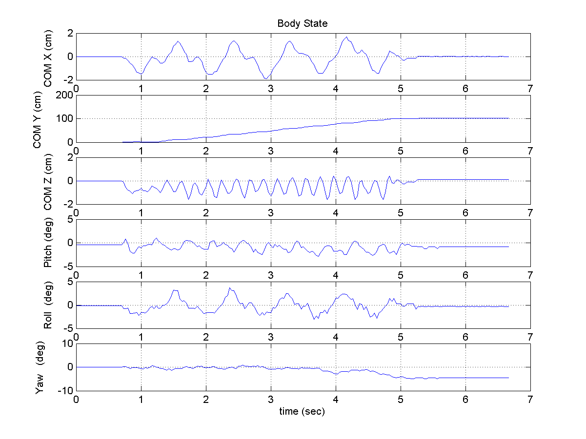
After the video has been captured and processed, we generate can generate a 3d plot of the position of each of the markers as a function of time, shown below in the left plot. We can process the position data taken from these three markers to determine the position and orientation of the robot as a function of time. A plot of the measured 6DOF motion of the robot frame is shown in the right plot.